District metered Areas - Why accuracy matters
Learn why accuracy is crucial in DMAs and why the TORPEE-MAG is ideal for such applications.
District Metered Areas: Why accuracy actually matters?
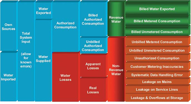
Reducing losses across drinking water distribution systems is thankfully becoming a worldwide top priority. Translated in Non-Revenue Water, it absolutely makes sense to recapture water being lost through leaks and not sold. Regulations are slowly implemented across the US (Water audits mandatory in some states) and in Canada (Quebec for example). The American Water Works Association (AWWA) and the International Water Association (IWA) published a water audit table (figure 1) showing a detailed breakdown of a water system production/Consumption and losses.

Figure 1: IWA/AWWA Water Audit Method: Water Balance
Using accurate flowmeters for the blue section is never questioned in our industry and the same applies to apparent losses (Source, Residential, Commercial and Industrial metering). Real losses quantification on the other hand has been approached with lower expectation, mostly due to flowmeter limitations and industry habit.
Data repeatability naturally became one key feature with DMA (District Metered Area) monitoring MNF (Minimum Night Flow Trending) as accuracy was not achievable with battery powered flowmeters.
Accuracy refers to the closeness of a measured value to a standard or known value whereas repeatability refers to the closeness of the agreement between the results of successive measurements of the same measure, when carried out under the same conditions of measurement. Having a strong repeatability without accuracy can be defended when managing a DMA with one single entry point and for MNF tracking purpose (hydraulic DMAs).
Experiences across North America have proven this model to be not sustainable for various reasons such as fire safety, water quality, distribution system design, etc. DMAs are therefore regularly set with multiple inlets and outlets, thus creating a situation where repeatability cannot be the main choosing factor for flowmeters. Also, new approaches such as virtual DMAs (No boundary valve closure, increase of monitoring points with flow, pressure, noise data remote collection) require ACCURATE AND REPEATABLE flow data as a base for all the top-end analysis. Even the most advanced algorithm/AI cannot turn weak data into a reliable and brilliant model.
Multiple flow monitoring points being a starting point when designing DMA’s (virtual or not), the next step is the flowmeter choice for flow data collection and KPIs tracking (Minimum Night Flow, ILI, water losses/connection/day, etc.).
Historically, our industry associates DMAs with either in-line magmeters or single point insertion magmeters (center line insertion) and for a large proportion, battery-powered devices. Using existing vaults is always preferred as a way to lower the overall set-up cost.
If one conducts a broad market survey of in-line magmeters, a few key points will naturally appear:
- High cost of installation (Unnecessary interruption of supply)
- No indication of accuracy on low velocities (Night flow hydraulic conditions)
- No indication of lowest stable velocity detectable
- Need to reduce the pipe size to increase the velocity and somehow overcome the two previous points. Thus, creating higher pressure head loss and consequently increasing the amount of energy needed to supply water throughout the network (rise in CO2 emission for pumped systems)
As mentioned previously, a large proportion of DMA flow monitoring applications require self-contained devices. This market expectation (long battery life) comes with a drawback which is rarely raised during the flowmeter selection: How often are measurement taken in order to maintain several years of battery life? The answer is definitely not real time. Having a slow sampling rate automatically impacts the flowmeter accuracy, stability, repeatability and also, its ability to catch rapid flow changes.
Single point insertion magmeters have one similarity with in-line magmeters which is the use of two electrodes to measure the flow. With the in-line mag, the water is going through a tube and the electrodes are embedded within the wall at specific locations (9 and 3 o’clock). As for the single point insertion magmeter, the sensor is inserted inside the pipe and the electrodes are positioned to be in the center line. It is worth noting that another type of installation (called 1/8th) is possible and mostly used for larger pipe when the center line cannot be reached safely (high velocities, probe too short) but with a high degree of inaccuracy.
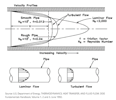
Manufacturers follow the ISO norm 7145-1982 (BS1042 section 2.2) and all state the fact that a fully developed velocity profile (figure 2) is needed to meet the accuracy, repeatability and stability claims.

Figure 2: Velocity profiles
Based on the hypothesis that the site velocity profile meets the previous requirement, the sensor will measure the maximum velocity (center line) and apply an insertion factor (blockage factor depending on probe size), a profile factor (value between 0.85 and 0.875) to calculate the average velocity, then used in the end to determine the flow rate (calibration and linearization applied to flow value).
If we now consider all of the above in a real-life distribution system, we then have a fair number of assumptions to make in order to confidently use flow data coming from a single point insertion magmeter:
- My profile is fully developed. Unlikely in most applications (upstream straight distance not respected, old metallic pipe with corrosion, profile distorted…)
- Performing a full velocity profile should help. Maybe. Again, two more assumptions must be made:
- Velocity won’t change during the process
- Profile remains the same at all times, which is not true in almost all water applications
- Sensor is correctly installed in the center line. Possibility for error if installation procedure is not followed precisely
All the previous points tend to demonstrate that having a plastic or a smooth pipe with very long straight distance is one of the only situations which can provide a fully developed symmetrical profile. It also shows that several critical milestones must be met on-site (similar to laboratory hydraulic test rig) to guarantee proper hydraulic conditions.
As in-line magmeters, battery powered single point insertion meters sample at best every 30 seconds to guarantee a decent battery life. Due to the location of the electrodes, they tend to measure lower velocity (some Manufacturers have claims down to ± 2 cm/s or ± 0.065 ft/s) but what about the accuracy and stability at low flows.
In refence to ISO norm 7145-1982, accuracy is commonly shown as ±2% of the reading value or ± 2mm/s (± 0.0065 ft/s) whichever is the greater. So, what does it really mean?
- Manufacturers can decide how they display their sensor’s accuracy
- By doing the math, 10 cm/s or 0.32 ft/s appears to be the trigger point
where ± 2mm/s or ± 0.0065 ft/s becomes more favorable
- At 5 cm/s or 0.16 ft/s, accuracy is ± 4% with high instability
- At 2 cm/s or 0.065 ft/s, accuracy is ±10% with high instability
Those accuracies are based on velocity and get much worse if we look at flowrates especially for single point meters due to velocity profile distortions at low velocities.
To summarize: Choosing the right DMA flowmeter is critical to the data quality and reliability for future analysis and processing.
FLOW-TRONIC’s Equal Area Multi-Point Insertion flowmeter has technical features that is fit for any flow application across a water system (bulk meter, custody transfer, DMA, etc). They have expended tremendous effort in conducting tests and research to find the best way to build and calibrate their electromagnetic averaging insertion sensor TORPEE-MAG.
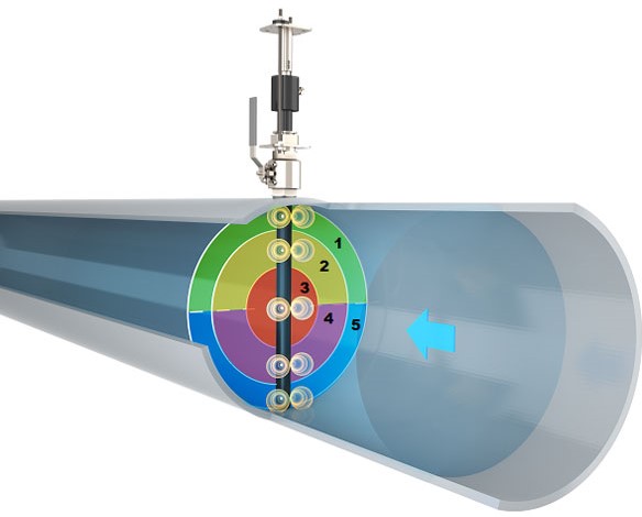
Multi-point velocity sensing electrodes located at Equal Area of flow (Only researched and validated positioning)

Figure 3: TORPEE-MAG measured areas
- Electrodes number and positioning facilitate installation in most pipe layout for optimum results
- Accurate distorted flow profile measurement by positioning the sensor in plane with the distortion
- Full traverse makes sensor positioning error impossible, eliminating the human error aspect of any install
- No site calibration (Velocity profiling) required
- Graphite electrodes for high stability at low flows (METAS tested. Results available on request)
- Bi-directional sensor with same accuracy both directions (Accredited hydraulic laboratory tested. Results available on request)
- ± 0.5% of Reading Value ± zero stability from 0.25 m/s or 0.82 fts to 6 m/s or 19.68 ft/s
- ± 0.8% of Reading Value ± zero stability from 0.02 m/s or 0.065 ft/s to 0.25 m/s or 0.82 ft/s
- IP68/NEMA 6P sensor which can be permanently submerged under 10 m (32.8 ft) of water and transmitter (tested to 10 m or 32.8 ft of water during 10 days)
- 2 seconds default sampling with 3-year battery life – Site replaceable with off-the-shelf alkaline batteries
FLOW-TRONIC believes that their customers deserve the best flow sensors delivering trustful and accurate flow data. Their rugged, solid-state TORPEE-MAG averaging insertion electromagnetic flow sensors with electrodes placed at Equal Area and sensing electrodes pairs calibrated individually, are made for those accurate and reliable flow measurements.

